The program is designed for analyzing vessels in computed tomography
In particular, studies of aortic stenosis and aneurysm
The program automatically:
removes bones
constructs the vessel's centerline
reconstructs the vessel's longitudinal view and a set of cross-sections
The Vessels program allows you to measure the diameter and cross-sectional area of a vessel at several points, compare the values, and display these points on MPR and 3D reconstructions
Display of the longitudinal view in straightened and curved planar reformations
Supports work with multiple vessels, saving construction results
After marking a vessel, the modules become available:
Stenosis Analysis and
Aneurysm Analysis
For correct operation, series in the non-contrast and arterial phases are required Features of head vessel analysis are described at the end of the section
Launching the Program
Click in the toolbar, group "Studies", on the "Programs" button
Click on the "Body Vessels" button
OR
Click on the "Head Vessels" button
Common Functionality
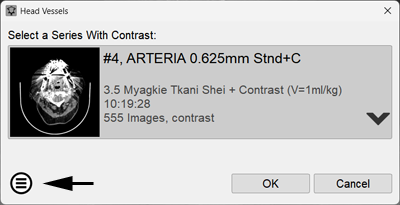
In the window that appears, check that the automatic selection of the series with contrast is correct, click the "OK" button
To select a different series, click the down arrow, then - on the series line
Click the OK button
Note:
You can always select a different contrast series for analysis during work
Left-click the "Choose another series for analysis" button in the lower part of the "Vessels" program panel, and select the desired series from the list that appears
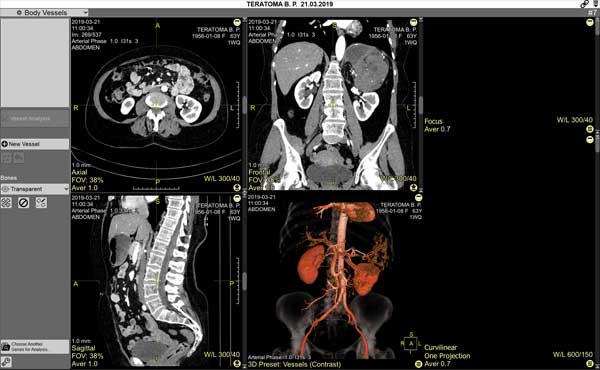
The screen will be split into 6 panels:
Four panels for vessel selection:
three standard orthogonal MPR projections
one - 3D model
Two panels with the tracing result: longitudinal view and cross-section
Images in them will appear after the vessel is constructed
Constructing the Vessel Centerline
Constructing the Guide Curve
Left-click the "New Vessel" button
Using left-clicks, construct a curve on the 3D model,
or any MPR projection (similar to constructing a 3D curve)
Click the "End Vessel" button
Or double-click the last point of the guide curve
For correct vessel tracing, it is necessary:
To set at least two points
Points should be located close to the center of the vessel lumen
The vessel between points should be continuous, without poorly contrasted segments
Notes:
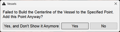
The program checks the 3D model for the presence of valid construction points
If a message appears:
check the correspondence of the series (arterial phase) and that the points are within the vessel lumen
If necessary, add intermediate points more often, adjusting their position so that the site of the vessel rupture can be passed in a straight line
or construct a new curve
Editing the Guide Curve and Vessel Centerline
Right-click on a point to delete an existing point (mouse cursor - on the point)
Right-click on the curve to add a new intermediate point (mouse cursor - on the curve)
Left-click and drag to move a point (mouse cursor - on the point: click and hold, move, release)
Left-click and drag to move the entire curve (mouse cursor - on the curve: click and hold, move, release)
To add a point at the beginning or end of the curve (not applicable for resulting straightened and/or curved planar reformations):
click the "Extend Vessel" button
Move the mouse cursor to the beginning or end of the curve
Left-click at the new location
To undo the last curve edit, use the "Cancel Vessel Editing" button
The longitudinal view and cross-sectional slices of the vessel will be constructed automatically
Switching the projection of the longitudinal view display - straightened or curved planar - is possible via the active overlay of the corresponding panel
The number of projections for displaying the longitudinal view - one or two - can also be specified there
The number and type of longitudinal projections can be set for permanent display in the "Vessels" Program Settings (see below)
Similar control of reconstructions and projections in the Vessel Analysis mode
Controlling Reconstructions Using Cursors
The program has four types of cursors:
3D cursor "yellow cross"
Acts the same as in MPR and controls the three standard, orthogonal MPR projections
Red linear cursor on the longitudinal view
The linear cursor on the longitudinal view controls scrolling through cross-sections and their corresponding MPR projections
Red linear cursor with an arrow on the cross-section
Rotates the longitudinal view when showing the straightened projection
If the longitudinal view is shown in the curved planar projection, this cursor does not affect it, and it can only be rotated using 3D rotations
Ring-shaped red cursor on the 3D model
Action is similar to the linear cursor without an arrow on the longitudinal view, allows scrolling through cross-sections
Removing Bones in the 3D Model
Automatic Bone Removal
is performed when there is a series of images without contrast agent and occurs automatically when the program is started
Correcting Automatic Bone Removal
If the program cannot automatically detect the non-contrast series, (for example, if there are several non-contrast series in the study) the program will ask to select the appropriate one
During work, this can be done forcibly by clicking the "Re-remove Bones" button in the program panel
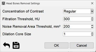
In the window that appears, click the down arrow, then - on the desired series For correct bone removal, the slice thickness of the non-contrast and arterial phase series must match or be close
Click the OK button
Cancel Bone Removal
Click the button in the program panel
Manual Bone Removal
If fragments remain on the 3D model after automatic bone removal, click the "Manual Bone Removal" button in the "Vessels" program panel
When hovering the cursor over remaining bone fragments, it becomes opaque
Move the mouse cursor over the remaining bone fragments in the 3D model and left-click
In case of erroneous removal of a vessel part together with bone, press the key combination
+
to undo the last action
To exit the mode, click the "Manual Bone Removal" button again, or press the key
Displaying Bones on the 3D Model
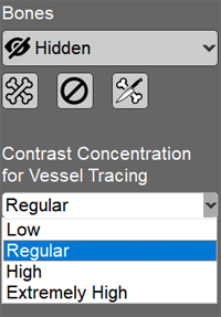
You can choose from the list in the "Vessels" program control panel, "Bones" (default - Transparent), or
Click the "More" button in the lower right corner of the 3D model panel
Select the bone display mode by clicking the corresponding item:
Transparent bones - for anatomical reference without obscuring vessels
Hide bones - completely remove from the 3D reconstruction
Show bones - bones are completely opaque, as on a standard 3D reconstruction
May obscure vessels
Re-remove bones - brings up the dialog for selecting a non-contrast series
Cancel bone removal - shows the complete 3D model with all structures
Construction of a New Vessel While Preserving the Existing One
The program allows working with multiple vessels in one study
Left-click the "New Vessel" button
Repeat the actions described above, starting with constructing the guide curve of the vessel centerline
Vessel List
Vessels are added to the program's vessel list, where you can select the desired vessel for display, name the vessel, or delete it
Selecting a vessel
In the vessel list, left-click the button "Vessel 1" (2,3...)
Renaming a vessel
In the vessel list, left-click the "Rename" button next to the selected vessel
Deleting a vessel
In the vessel list, left-click the "Delete" button next to the selected vessel
Saving Construction Results
The guide curve and reconstruction results are automatically saved upon exiting the program in the Finds list
To display them again on the screen, click on the "Vessels" item of the Finds list in the Preview Bar
Program Settings
Click in the upper left corner of the series header on the "Vessels" button
In the menu that appears, click on the item - "Settings"
Specify the required parameters of the resulting projections, as well as the type of preferred reformations and the number of their projections:
Changes are displayed dynamically on the screen
Exiting the "Vessels" Program Mode
Click on the "Exit Mode" item in the "Vessels" menu
The screen splitting will return to standard
Features of the "Head Vessels" Program
Due to the close proximity of bone structures to vessels, settings for controlling vessel contrast are introduced for correct bone removal and vessel tracing:
At startup, in the series selection window
When re-removing bones from the program panel
During vessel tracing
Set the parameters according to the vessel contrast in the study
Note: the button in the toolbar is intended for engineers!
Useful Tips
If the vessel has a complex configuration, two construction points may not be enough
In case of a complex vessel configuration and close location of bones, it is better to construct the vessel's reference curve on axial scans (similar to cMPR)
Too sharp curve bends create artifacts on the resulting surface
When constructing a curve, hide the 3D cursor and lines (key on the keyboard) so they don't interfere
After construction - return them to the screen in the same way
During construction or curve editing, enlarge the panel by double-clicking on it, or click the icon in the upper right corner of the panel
After editing - return its size in the same way
Hold down the right and left mouse buttons and rotate the 3D model for optimal vessel display on the screen


 "Re-remove Bones" button in the program panel
 button in the program panel
 in the "Vessels" program panel
 +
+  to undo the last action
 key
key
 in the lower right corner of the 3D model panel
 next to the selected vessel
 next to the selected vessel
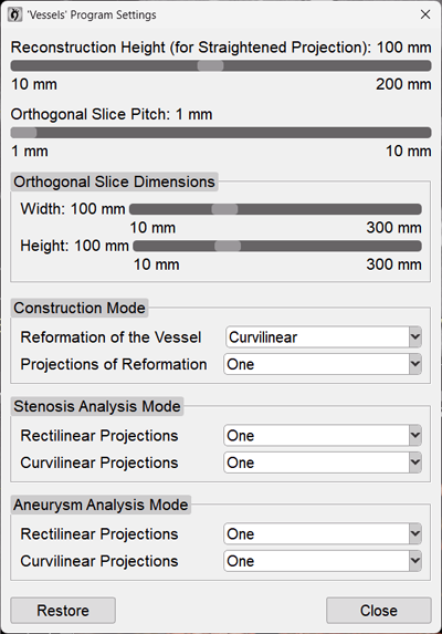
 in the toolbar is intended for engineers!
 on the keyboard) so they don't interfere
 in the upper right corner of the panel