The cardiothoracic index is the ratio of the maximum diameter of the cardiac shadow to the internal diameter of the chest, measured above the domes of the diaphragm on a frontal X-ray, multiplied by 100
Construction in the Application
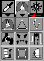
Click on the button in the toolbar
Construction of the measurement in the application (on a frontal radiograph):
Click on the dot in the far right corner of the heart shadow
Click on the dot in the far left corner of the heart shadow
With two clicks of the mouse, draw a line segment perpendicular to the spine at the widest part of the rib cage, above the diaphragm
The result will be calculated automatically:
In children, the normal value can reach 55%
In adults, three degrees of increase in the cardiothoracic index are distinguished:
Grade I - slight increase - from 50 to 55%
Grade II - moderate increase - from 56 to 60%
Grade III - significant increase - over 60%
Longitudinal Flat feet
The angle of the longitudinal arch of the foot is determined on radiographs by constructing a triangle
Vertices of the triangle:
Inferior point of the head of the first metatarsal bone
Inferior point of contact between the bony surfaces of the navicular and cuneiform bones of the foot
Inferior point of the calcaneal tubercle
Construction in the Application
Click on the button in the toolbar.
Construction of the measurement in the application is performed using a simplified scheme
For reference:
Normally, the foot arch angle is 125 - 130 degrees
On the X-ray images, three straight lines are drawn corresponding to the longitudinal axes of the first and second metatarsal bones and the axis of the proximal phalanx of the first toe
Construction in the Application
Click on the button in the toolbar
Construction of the measurement in the application is performed using a simplified scheme by clicking on:
ends of the longitudinal axis of the second metatarsal bone
ends of the longitudinal axis of the first metatarsal bone
ends of the longitudinal axis of the proximal phalanx of the first toe
Points must be placed in the sequence indicated in the diagram!
For reference:
Flat feet Degree
Angle between 1st and 2nd Metatarsal Bones
Angle of Deviation of the 1st Toe from the Axis
1
10 - 14 deg
15 - 20 deg
2
15
30
3
20
40
4
more than 20
more than 40
Acetabular Angles
This measurement is intended for examining adults; for children - see below - "Hip Dysplasia"
Acetabular angles are calculated using the Hilgenreiner scheme
The "teardrop figure" is used as the lower landmark, and the upper edge of the acetabular roof as the upper landmark
Construction in the Application
Click on the button in the toolbar
Construction of the measurement in the application is performed by clicking sequentially on:
point of the roof of the right acetabulum
"teardrop figure" of the right acetabulum
"teardrop figure" of the left acetabulum
point of the roof of the left acetabulum
The result of angle calculation will occur automatically
Normally, the angle is 33º - 38º
A value of 39º - 46º is considered intermediate
An angle greater than 47º is considered acetabular dysplasia
Hip Dysplasia
This measurement is intended for examining children; for adults - see above - "Acetabular Angles"
Calculation is performed using the Hilgenreiner scheme
Angles are formed by a horizontal line connecting the triradiate cartilages (Hilgenreiner's line) and lines that are extensions of the acetabular roofs
The values H and D are also calculated
Construction in the Application
Click on the button in the toolbar
Construction of the measurement in the application is performed by clicking sequentially on:
projection point of the roof of the right acetabulum
right triradiate (Y-shaped) cartilage, upper point
left triradiate (Y-shaped) cartilage, upper point
projection point of the roof of the left acetabulum
middle of the metaphyseal plate of the proximal part of the left femur
middle of the metaphyseal plate of the proximal part of the right femur
The result of angle calculation will occur automatically
H - vertical displacement of the femoral head relative to the acetabulum - distance from Hilgenreiner's horizontal line to the middle of the metaphyseal plate of the proximal part of the femur
Normally, this value is equal on both sides and ranges from 9 to 12 mm
The D value indicates lateral displacement of the femoral head relative to the acetabulum - distance from the bottom of the acetabulum to the vertical line (value h)
Normally equal on both sides and should not exceed 15 mm
Normal values in children and degrees of dysplasia (Graf's table):
Age
Normal
1
2
3
3-4 months
25-30 deg
30-35 deg
35-40 deg
more than 40 deg
5 months - 2 years
20-25 deg
25-30 deg
30-35 deg
more than 35 deg
2-3 years
18-23 deg
23-28 deg
28-33 deg
more than 33 deg
Shortening of the Lower Limb
The application is based on a method used in AFGA stations
Draw a segment between the centers of the femoral heads by clicking on their centers
Move the mouse down to the lower articular surfaces of the tibial bones
Click to fix one of the surfaces, move the mouse to the second articular surface and click again
The application will display the difference in limb lengths in mm
Note: In case of pelvic tilt, it is better to start construction from the lower articular surfaces of the tibial bones
Cobb Angle
The application uses the 1st variant of the Cobb method
The scoliosis angle is formed by intersecting perpendiculars, drawn towards each other from lines passing along the lower surface of the upper and the upper surface of the lower neutral vertebrae
Click at the beginning and end of the first segment along the lower surface of the upper vertebra
Click at the beginning and end of the second segment along the upper surface of the body of the lower vertebra
The application will display the Cobb angle value
For the 2nd variant (with significant spinal curvature), use the standard angle tool (key on the keyboard)
The scoliosis angle is formed by intersecting lines passing along the lower surface of the upper and the upper surface of the lower neutral vertebrae
Classification of scoliosis by the angle of frontal curvature of the spine according to Cobb (V. D. Chaklin, 1961):
 in the toolbar
Construction of the measurement in the application (on a frontal radiograph):
in the toolbar
Construction of the measurement in the application (on a frontal radiograph):


 in the toolbar.

 in the toolbar

 in the toolbar

 in the toolbar

 in the toolbar

 in the toolbar
 on the keyboard)
 in the toolbar


 key on the keyboard